Let Bluetooth Guide My Bike (Part 3: Power Consumption)
This is the third post in a series documenting my (mis)adventures trying to create a bicycle navigation aid. See Part 1 Part 2 The Code. This could also be seen as a standalone adventure trying to reduce the power consumption using Bluetooth on the ESP32 microcontroller, because oh boy, this part was a doozy:
The Easy Part
As I mentioned in Part 1, the plan was to use an ESP32-based, LCD and battery charger equipped development board to display speed and navigation information pushed from an Android phone over Bluetooth Low Energy. I was hoping that by using a powerful microcontroller, high(er)-level Arduino libraries, and a drop of C++, I could avoid most of the tedium usually associated with developing this sort of thing. Using the PlatformIO IDE, it took a bit of hacking to get both the Android core and ESP32 framework to coexist, but a bit of scrounging around on Google helped me piece together the platform.ini file magic to make it all work:
framework = arduino, espidf
...
platform_packages =
	platformio/framework-arduinoespressif32 @ https://github.com/espressif/arduino-esp32.git#idf-release/v4.0
Espressif provides a development framework called ESP-IDF that includes a C library to more easily interface with the hardware, along with a compiler and some other tools. The Arduino core itself is provided separately. This often means that the IDF libraries can often get out of sync with the Arduino core, thus leading to compile errors if the versions don’t match up correctly. In this case, I had to pick the #idf-release/v4.0 branch in order for it to work “out of the box”.
The Arduino IDE gets around this problem by including a pre-compiled Arduino core, but unfortunately this prevents you from configuring the framework to enable or disable certain features, which will become relevant later.
The rest was pretty straightforward. The only major hitch was uploading the sprite for my “compass” needle. The LCD library (Wonderful Library, by the way) expects colours in a 16-bit RGB565 format, with 5 bits for red, 6 for green, and another 5 for blue (our ancestors spent a lot of time staring at trees: the human eye is especially sensitive to green). After finding a few sorta-but-not-really-what-I-need solutions online, I just wrote a simple Python script to translate the image into a C-style array. After that it was a simple matter of making the display update every ~1.5 seconds or so in a loop in order to keep power consumption down without risking getting lost.
After a bit of plumbing I was able to take my navigator on its maiden voyage. It worked quite well, except for the fact that after about 1.5 hours - it died.
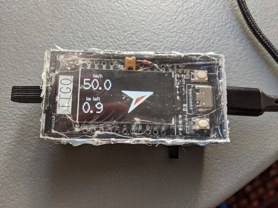
Yes, this picture was taken while using a GPS simulator to test; I’ve only ever rode my bike at 50km/h while bombing down a hill and I sure wouldn’t have been trying to take a picture of something in the process.
The Fun Part
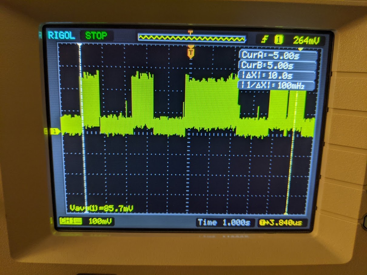
I had a 1.8Ω resistor and an old USB extension cable lying around, so I used it to make a rudimentary current probe. And my oscilloscope revealed just how much of a power glutton my navigator was:
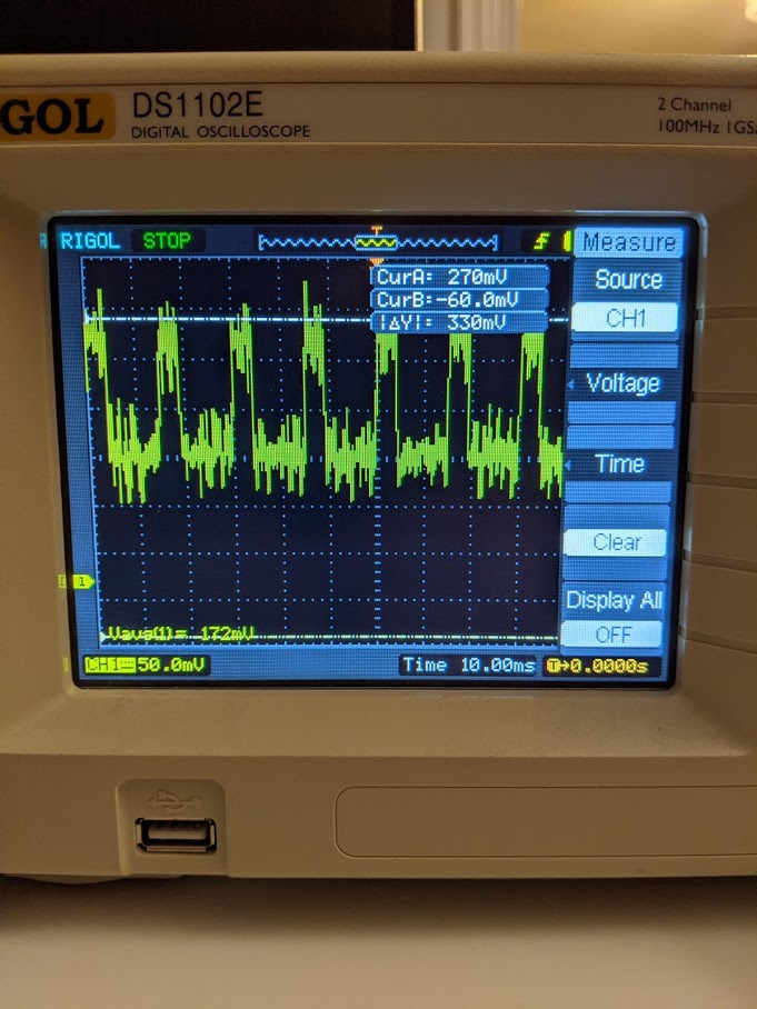
There are two important things to notice here: The first is that the period of those power consumption spikes is roughly 10ms, which is a far cry from 1.5 seconds. The second is that the average voltage is ~172mV. Let’s do some simple math:
- V = IR => I = V/R
- I = 0.172 / 1.8 => 0.095555
So about 100mA at 5V, but a LiIon cell is only 3.60V (nominal), so we multiply 0.095555 * (5/3.60) = 133mA. Our battery is only 220mAh, which means that we can expect under 2 hours of battery life on a single charge. “Low Energy”, my eye! Let’s try to improve it.
Dormez-Vous?
The most obvious way to reduce power in a microcontroller is to simply have it not run at all. Most microcontrollers offer sleep modes which will suspend the CPU and/or some of the peripherals in order to save power. For example, say you want to take a temperature measurement every 10 minutes and send it to a server, do you really need the CPU running at full blast for the other 9.9999 minutes? Of course not! The ESP32 approaches this by providing three major sleep modes:
- Modem Sleep: Allow the Bluetooth/WiFi modem to turn itself off during periods of inactivity, but otherwise keep the system running;
- Light Sleep: Turns off almost everything except the Real-Time Clock (RTC) and Ultra Low Power Coprocessor (ULP, more on this later), keeps data in RAM;
- Deep Sleep: Turns off everything except the RTC and ULP, contents of RAM are not preserved.
Modem sleep with light sleep for the 1.5 sec delay between readings seemed like a good place to start. I found this super-helpful GitHub issue detailing how one goes about reducing BLE power consumption. Here’s the short version for the hyperlink-averse:
- Enable “Tickless Idle” in FreeRTOS, which tells FreeRTOS to put the ESP32 into light sleep if the system is idle;
- Enable Bluetooth Modem Sleep, which lets the modem power off during periods of inactivity;
- Tell the RTC to use an external clock source provided by a 32kHz crystal, as the internal oscillator isn’t accurate enough for Bluetooth modem sleep;
- Enable light sleep mode when you start the program. Also reduce the max CPU clock speed to save power.
All this “enabling” is done using the menuconfig tool, similar to how you configure a Linux Kernel. Simply run pio.exe run -t menuconfig in the directory of your project, and a menu appears that lets you configure the various components of the ESP32. While we’re at it, we can tell FreeRTOS to run only on one core, more power savings!
I was happily toggling away at the various options when I realized I had a big problem: We want the RTC to run with an external 32kHz crystal, but will a $8 development board even have such a (relatively) expensive component? Haha, nope.
No Clock for You
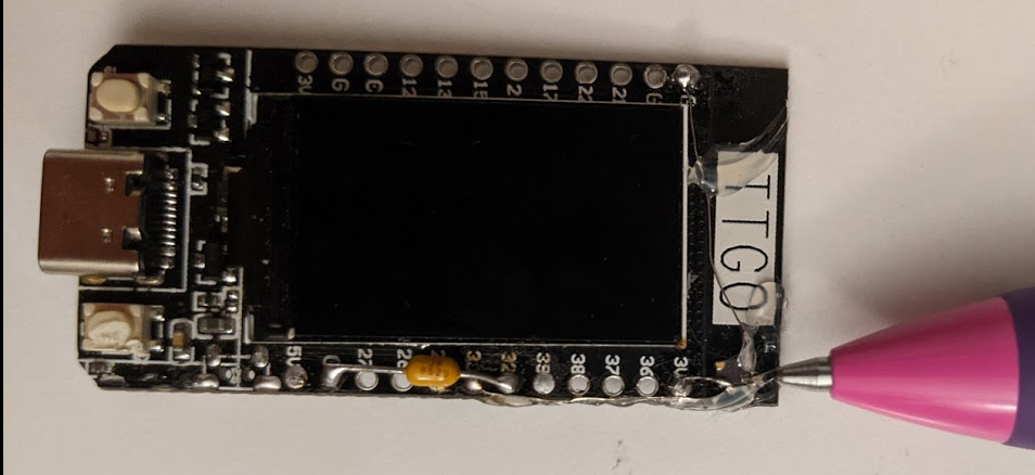
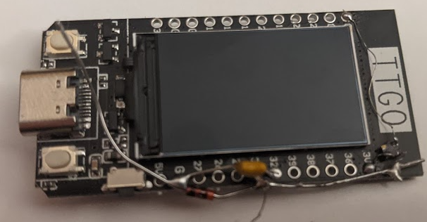
Just because it doesn’t come with a crystal doesn’t preclude us from adding one. Luckily, the dev board does expose the appropriate pins (32 and 33), so after ordering a crystal and a pair of capacitors from DigiKey, I was in business. I hackily soldered on the crystal + capacitors, and…nothing. The ESP32’s system log still reported no external clock input found for the RTC. After fiddling with it a bit, I concluded maybe the long traces from the chip to the edge of the board were too long to get the crystal to oscillate properly. Not one to be deterred, I went to my next option: An oscillator.
An oscillator is basically a crystal, but with an inbuilt amplifier circuit that provides a nice square wave as an output. It was a bit trickier to solder on since it requires 3 pins (Power, Signal, Ground) and we still need a capacitor as per the ESP32’s hardware guide:
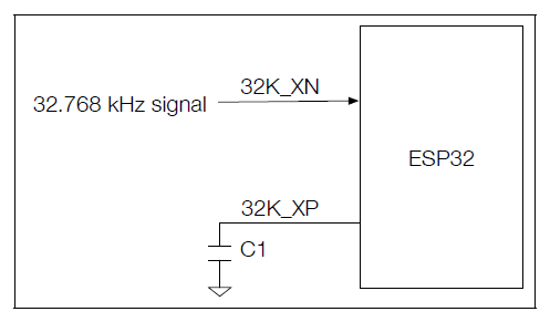
But the menuconfig tool tells a different story:
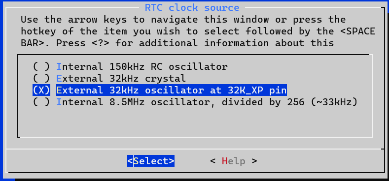
Notice that? The design guide says that the clock signal should be connected to 32K_XN, but the menuconfig tool says it should be connected to 32K_XP. Don’t worry, I’m here for you: After some trial and error, it seems like menuconfig is right: It should be connected to 32K_XP.
But even with all that, it still didn’t work! According to the design document, the clock signal has to be between 0.6V and VDD. The design doc references a VDD_SDIO, which could be driven by an internal 1.8V regulator. So I tried a simple solution: Let’s put a silicon diode between the clock signal and ground. That way, the signal should effectively be clamped to 0.7V or so.
And glory be! After two trips to DigiKey and some microsurgery with a soldering iron and tweezers, the ESP32 finally recognized the clock! In the meantime, I also got a proper USB current measuring tool. It reported a current consumption of ~70mA at 5V - much better!
The last step is to modify the KConfig file for menuconfig slightly to allow the Bluetooth module to use the external oscillator as its sleep clock source in framework-espidf/components/bt/KConfig :
config BTDM_LPCLK_SEL_EXT_32K_XTAL
                    bool "External 32kHz crystal"
                    depends on ESP32_RTC_CLK_SRC_EXT_CRYS || ESP32_RTC_CLK_SRC_EXT_OSC
                    ...
Power Underwhelming
70mA still seems like quite a bit of current, can we do better? One thing I noticed is that since the bluetooth modem was always “connected”, it was constantly waking the ESP32 out of light sleep. I decided to try disconnecting the modem before entering light sleep and reconnecting it upon wake-up. Although this caused a current spike when reconnecting / reading data, the current monitor displayed ~25mA when it was sleeping, which is already a major improvement.
The next big power hog is the backlight for the LCD. This is kind of important, because it’s responsible for allowing us to actually see the screen, but maybe running it at full-blast was overkill. I decided to try reducing it to 50% using the ledc module, which the ESP provides to control the brightness of an LED with PWM (Convenient!). That worked well…when the device wasn’t sleeping. Remember when I said the sleep modes disable peripherals to save power? I wasn’t kidding - once it enters sleep mode, the ledc module works no more, leaving you with a black screen until it wakes up.
You can tell it to “lock” the state of a GPIO before entering sleep mode, but this just brings us back to our original problem of the backlight being at full power. How can we reduce the brightness of the LCD backlight in sleep mode?
ULP is Right for Me
I mentioned in passing a peripheral called the Ultra Low Power Coprocessor (ULP). Let’s dig in a little deeper. The kind folks at Espressif know that you might, for example, want to wake the ESP32 up based on a periodic sensor reading. To that end, they included a little microcontroller-within-a-microcontroller called the ULP. It sips power and runs while the rest of the system is sleeping at the expense of a (very) limited instruction set. This should help us control the backlight despite the ESP being in sleep mode.
To create a ULP program, you have to use some provided CMake functions, which will then allow you to access the program binary from a C source file of your choosing. From there, you can upload the program to RTC memory using the ulp_load_binary function. Then you set a period for the program to be repeated using ulp_set_wakeup_period (it runs until it hits a HALT instruction), and then finally run it using ulp_run. The process is well documented by Espressif here. The only hiccup is that for it to work with PlatformIO it has to be named ulp_main and put in its own directory in the project.
The ULP is clocked at 8MHz, so if the PWM frequency for the LED is, say, 500Hz, we can dim the brightness to 50% by telling the ULP to hold it “on” for 8000 ticks at a wake-up period of 2ms:
    WRITE_RTC_REG(RTC_IO_TOUCH_PAD0_REG,RTC_IO_TOUCH_PAD0_HOLD_S,1,0)
    WRITE_RTC_REG(RTC_GPIO_OUT_W1TS_REG, RTC_GPIO_OUT_DATA_W1TS_S + 10, 1,1)
    WAIT 8000
    WRITE_RTC_REG(RTC_GPIO_OUT_W1TC_REG,RTC_GPIO_OUT_DATA_W1TC_S + 10,1,1)
    WRITE_RTC_REG(RTC_IO_TOUCH_PAD0_REG,RTC_IO_TOUCH_PAD0_HOLD_S,1,1)
    HALT
The fun thing about the ULP is that you have to write a ‘1’ to a distinct register to set and clear, respectively. Even more fun, pins for the RTC don’t follow the same numbering as the GPIO. While looking for an example to follow, I came across this GitHub Repo which just so happened to use the same pin. You can also find a full table in the Documentation.
I also had to modify the header file in the Arduino TFT library to wrest control of the backlight pin. And sure enough, the screen was about half as bright (yet still very much legible), and the current draw was down to 15mA at idle.
We see now that the chip is indeed entering an idle state every 1.5 seconds (indicated by a marked drop in current consumption), and the current draw at 5V is now calculated to be ~66mA (assuming my oscilloscope is accurate at that scale). Although the current draw drops down to about 15mA at idle, it spikes back up to over 100mA while reconnecting, which itself can take a 1-2 seconds.
With our backlight power reduction taken into account, I’d say the current draw is comparable to when we were simply relying on modem sleep, assuming we maintain our update interval of ~2 seconds. That’s a bit of a bummer.
The End?
Unfortunately I couldn’t find any more voodoo to convince this thing to sip power. It might simply be punishment for taking a shortcut and not building a custom circuit around a more specialized microcontroller like the TI CC2640. At any rate, we should now expect at least 4 hours on a charge - more if we reduce the refresh rate or use a bigger battery. I don’t think that’s too shabby, especially for a project that costs roughly $10 in materials (shipping excluded).
I think ultimately the advantages provided by the Arduino library with the ESP32 are a bit of a double-edged sword, since it can be difficult to get it to work with the latest-and-greatest IDF and they already provide a hardware-abstraction library to save you some time. Also I noticed that the Arduino libraries can occasionally have bugs, such as a double-free when resetting the BLE client. They are pretty good about fixing them, but it gets tricky due to the aforementioned compile issues. I guess staying old-school sometimes has its advantages :)